
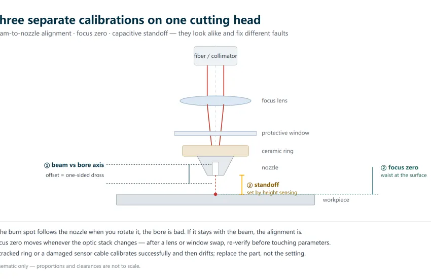
Laser Cutting Head Calibration: Three Jobs, Not One
Most calls that start with "we need to calibrate the head" end somewhere else: a worn nozzle, a hazed protective window, a ceramic ring with a hairline crack. That is not because calibration is rare — it is because the word covers three different jobs, and only one of them is usually the culprit.
Calibration is three different jobs
On a fiber cutting head, "calibration" gets used for all of the following, and they have nothing in common except that they are all done with a wrench and a test cut:
| Job | What it actually sets | Typical symptom when it is off |
|---|---|---|
| Nozzle centring (beam-to-nozzle alignment) | Whether the focused beam passes through the middle of the nozzle bore | Dross on one side only; the kerf leans; one flank of the cut is rough and the other is clean |
| Focus zero | Where the beam waist sits relative to the work surface — the reference the whole parameter table is written against | Cut quality falls off across all thicknesses at once; the same program that worked last month now under-cuts or over-burns |
| Height sensing calibration | The relationship between the capacitive signal and the real standoff | Height alarms, hunting on thin sheet, or a head that runs visibly too high or too low |
Keeping these separate matters because the fixes are different, and doing the wrong one makes the machine worse. Re-centring a nozzle to cure a focus problem will move a good alignment out of position.
Before you calibrate: five things that make calibration look broken
If any of these is true, calibration will appear to fail no matter how carefully it is done. Check them first — in a workshop, this is where most of the time is saved.
- The nozzle bore is worn or oval. A damaged bore cannot be centred, because there is no axis to centre on. Hold it up to a light; an oval or chipped orifice is the end of the conversation.
- The protective window is hazed or burnt. A window with a brown patch scatters the beam, and the resulting spot is not round no matter where you put the nozzle.
- The ceramic ring is cracked. The height loop reads through it. A hairline crack shows up as a drifting standoff, which looks exactly like a calibration error.
- The focus lens is seated wrong, or the wrong one is fitted. A lens in backwards, or a different focal length than the parameter table assumes, moves focus zero without any error message.
- Assist gas is low or leaking. Poor gas flow produces one-sided dross that mimics an off-centre nozzle.
Nozzle centring, and the trick that tells you which part is wrong
The goal is simple: the beam axis and the nozzle bore axis have to coincide at the tip. What makes it confusing is that two different faults produce the same one-sided dross — the nozzle is crooked relative to the beam, or the nozzle bore itself is asymmetrical.
There is a reliable way to tell them apart. Do a low-power pierce onto a piece of tape or thin sheet held at the nozzle tip, note where the burn mark sits relative to the bore, then rotate the nozzle 90° and repeat:
- The mark moves with the nozzle → the bore is off-centre or worn. Replace the nozzle. Adjusting alignment will not fix a bad bore.
- The mark stays in the same place relative to the beam → the beam is off the mechanical axis. Now centring is the right job.
| What the pierce mark looks like | What it means | Do this |
|---|---|---|
| Round, centred in the bore | Alignment is fine | Stop here; look elsewhere for the cut problem |
| Round but offset to one side | Beam off axis | Centre the beam to the nozzle, then re-test |
| Elongated, teardrop or double | Bore worn or damaged, or two reflections | Replace nozzle first, then re-test before touching alignment |
| Very large and fuzzy at low power | Focus far from zero, or a hazed window | Check focus zero and the window before centring |
Focus zero: the reference everything else is written against
Focus zero is not a setting you "get right" once — it is a reference that moves whenever the optic stack changes. Change the focus lens to a different focal length, change the window thickness, or reseat a cartridge, and the zero has moved even though nothing was "adjusted".
The practical test does not need a special instrument. Cut a ramp or a stepped sample at a fixed power and gas setting, then look at where the kerf is narrowest and the dross lightest. That point is your true zero. Set it, then verify on a flat sample at the thickness you actually run.
| What the cut shows | Focus is probably | Next step |
|---|---|---|
| Wide kerf, heavy dross, rounded top edge | Too high (waist above the surface) | Lower the zero, re-test on the same sample |
| Narrow kerf, deep striations, spatter shower | Too low (waist below the surface) | Raise the zero, re-test |
| Good at one thickness, poor at another | Zero is acceptable; the focal length is wrong for the range | This is a lens choice, not a calibration |
| Changes during a shift | Thermal drift from an absorbing optic, or a loose cartridge | Check the window and lens seating, not the calibration |
Why another machine's number will not transfer. The focus offset published by a colleague is only valid for the same head, the same lens focal length, the same window thickness and the same mounting stack. Copy the number, and you have copied someone else's optics.
Height sensing: calibrate the loop, not the symptom
The capacitive loop runs from the ceramic ring and head body, up the sensor cable, into the controller. Calibration sets the relationship between the signal and the real standoff — but it can only be as good as the loop. A damaged cable or a dirty ring will calibrate "successfully" and then drift.
- Clean the ring and the nozzle seat. Contamination changes capacitance directly.
- Fit a good nozzle. The sensing geometry includes the nozzle.
- Set the standoff with a gauge or the controller's calibration plate, following the controller manual for the numeric step.
- Verify by moving the head up and down in manual mode and watching the readout: it should return to the same value at the same physical height, repeatedly.
| Symptom | Most likely | Check |
|---|---|---|
| Alarm at the same point in every program | Cable damaged at a specific drag-chain bend | Flex the cable there by hand while watching the readout |
| Readout drifts over a shift | Connector resistance changing, or a cracked ring | Reseat connectors; inspect the ring under a lamp |
| Hunting on thin sheet only | Signal noise, or gain tuned against a bad signal | Cable and shield first, then gain |
| Consistently high or low by the same amount | The calibration itself | This is the one case where recalibrating is the fix |
When calibration is the wrong fix
Some faults look like calibration and cannot be fixed by it. Recognising these quickly is worth more than any procedure on this page.
- A burn spot or dark dot on the protective window. The optic is absorbing; no amount of alignment recovers the beam.
- A cracked ceramic ring. The loop is open. Replace it, then verify the height reading.
- An oval or chipped nozzle bore. There is no axis left to align to.
- A focus lens with a halo or rainbow ring. The coating has degraded and the lens is scattering.
- A head that took a crash. Check the retaining cap, the seat and the ring before spending an hour on alignment — a bent cap will not hold a centred nozzle.
How often to do it
Recalibrating on a schedule is less useful than recalibrating after specific events. In practice, do it:
- after any crash or tip-up strike;
- after changing the nozzle type, the ceramic ring or the protective window;
- after changing the focus lens, especially to a different focal length;
- after transport, re-levelling, or any work on the gantry;
- and when a parameter set that used to work stops working across all thicknesses — that is the signature of a moved reference, not a bad parameter.
What is not a reason to recalibrate: a problem that appeared mid-shift on a machine that was fine in the morning. That pattern is almost always a consumable reaching its end, and recalibrating will mask it for a few hours and then fail again.
One honest limitation
The tolerance figures — how far off centre is acceptable, how many microns of focus offset matter — live in each head manufacturer's manual, and they differ between heads of the same brand. We do not publish a universal number, because there isn't one. What we can do is supply the parts that make calibration hold: a bore that is actually round, a ring that is not cracked, and a window that is not absorbing.